(Part of Our Phase #3)
Our Custom Stub Switches
B.A.D. Great Northern Railway
Becky And Dave's Private Railroad
See How We Build These In Place Switches
Travelin Light
Copyrighted - MP3 file
"the grilled Cheese Band"

Switch almost finished ... Derailer guards placed and almost ready to add splice bars and weld into place. This is also where we will be building 2 more switches for our Y to turn our train around and run in the opposite direction. Before this though we have to build the one on the other side of our new tunnel back into our main line.
For phase 2 I had Mel Harris build me the 2 left and right hand switches we needed and had a crew of buddies help us put them in .... But for our phase 3 loop my neighbor and mechanical engineer & steam train engineer Dave Moeller and I are building 4 custom in place stub switches by ourselves. We are building this first more difficult stub switch directly into our existing curve and straight because we want to keep our main line straight on thru the switch and not into and S curve back into & over the bridge. Becky and I want to keep our large 2nd phase loop mostly in tact. Dave Moeller came up with the idea to shorten the curve, which has a straight in the center of it, out of that loop by 6'. It now runs on over to and thru our tunnel. By moving the track over 6' we can run another parallel track along side our existing tunnel and train barn track ... use the existing wall and foundation to make a 2nd tunnel and train barn next to the existing one sharing a center wall. We could then also move the siding over to the new outside wall. This way we add another switch back into our main line at the exit of both tunnels back into our main loop again. And .... Then the new loop coming back into the existing tunnel would not need a switch at all. Our other 2 switches will be added between our new bridge loop and our old existing (Becky's Loop) to make a Y to turn our entire train around so we can run in both directions.
Stub switches should be used for all narrow gauge trains according to Mel Harris our engine builder ... they support the heavy engines much better than the long tapered pointed rail switches do.
I hope sharing the materials and this build sheet by photos will encourage some others out there to try the same. This is for those that already have an existing loop and want to branch out ... In a few days one can have a stub switch set up in line with your original track so you don't have any down time while you finish the frog and build your new project at your leisure.
We can use our old loop already. We will lock it in that position till I can build the track from the bridge to the straight. We will then put in the frog and derailer guard and the track for the new straight section out of the switch continuing on to our next loop out over our new all steel Warren Truss railroad bridge and back over our other land filled bridge on the other side. Below are some photos of the switch as we are building it. Our in place curved switch will have a unique straight frog on one side and a curve cut in by hand by Melvin Harris on the curved side to perfectly match our existing in place curve we have used for a couple years now.

First = Place the support tubes and the new projected rail in place
To get the general idea, it really helps to visualize what you have to do.


Yellow = 2" x 1" x 1/8" Channel
Red= 2"X 1/2" Flat Bar
Light Blue= 1/2" spacers tack welded on for the stub switch's 2" x 1/2" flat bar to pivot on. You must have the height of the tail of the pivoting stub rail the same height of the 2" Channel it will be sliding on .. so ... 1/2" spacer and the 1/2" flat bar tie = 1" .... the height of all our 2" wide channel steel ties. (these steel ties never lose gauge or ever need any maintenance.)
Green = 1/2" X 2.5" bolt thru a 1/2" hole ... use your drill press.
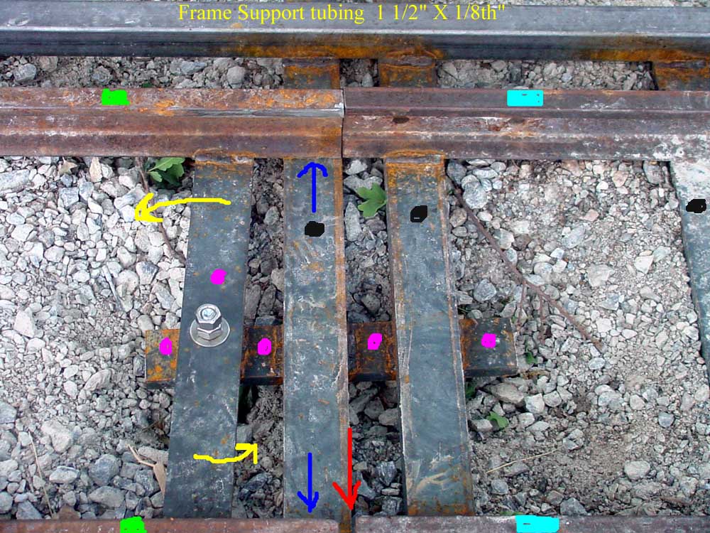
Green = Swing or pivoting stub switch section
Yellow = Shows direction of pivot ... switch is now in the straight thru position
Magenta = all the 2" x 1/2" Flat bar
Black = Channel ties
Blue = Do not weld the rail to this channel ... it is the pivoting tail of the stub switch
Light Blue = This is the old straight section we unbolted the track here and added another 2" channel here at the end for support and to have there to weld the pivot support flat bar under.
Red = The space necessary to swing and pivot the stub switch to the curve section. Before welding all of this in place, clamp everything securely first and test it out to get the general space needed. After it's welded you only need to remove the bolt to lift it out and adjust more where necessary. You can do this until you weld the front of the switch to the top of the 2" x 1/2" flat bar that goes to the switch stand and on out below the support tube on the other side ... Going all the way across holds the front part of the stub switch down rather than just by gravity alone .... this should be the last thing you do when all else is finished.

Blue = support tubing
Red = The old original curved track leading into our old loop.
Red Arrow = Direction the path of the stub switch must travel from the straight to the curved.
Light Blue = The stub switch in position to take the train straight thru down the new straight we are building to go across our new bridge. The straight rails in that align with the stub switch are to be the new rails ... Do not weld these new rails into place till the frog, the inner rail and both the inner derailer guards are in place ... If your new project is to be part of a curve it would be just the opposite. But, in the mean time this switch is totally functional into your old existing layout!.
With a new switch in an existing straight as our next 2 switches will be, will be 30' long with about a #8 switch as they will be on our main lines and we will build the curves to match the frogs and have a very smooth transition from the new curve to the straights.
Yellow = Weld this 1/2" flat bar that goes to the switch stand to the rail but not the side supports... BUT ... YOU MUST ADD A 1/8TH INCH SPACER between the bottom of the rail and the top of the switch stand bar! .... This allows the switch to move freely. I must make a confession here ... Dave & I thought our switch was so level and smooth we didn't need this spacer ... So being the over confident person I am I put full length 7018 stick welds on it instead of just a tack weld ... Well ... we screwed up ... the friction on the bottom of the support bar and the switch stand bar was so great we could only tap it over with the sledge hammer ... long story short I had to grind all of those welds off ..... But .. if you ever look at our switch ... It looks perfect as we turned the bar over, added our spacer on top of the other side and the screw up is now on the ground side..... Looks like we knew what we were doing. (; > )
Magenta Arrow = DO NOT WELD the rail to this channel tie .... it must slide on it to go from straight to the curved section of track.

5/22/06 ... Our first trip thru the switch today to Becky's Loop ... our old existing loop. I was going to just move this end of the loop across the ravine on the other side of the bridge and tie it back in without any switches at all. I was going nuts with the GPS and laying out the move ... Would not only have had to have taken it all apart plus moving all the ballast but cut it up a lot to fit! Becky said why in the world would you even think of doing that?! Plus all the down time on the loop that goes thru the tunnel, etc. .... So ... This is now named "Becky's Loop" ... She saved it! ... And it turns out that our down time off our old loop was only 2 days this way! When it gets down to it the right way is always the best way. Besides .... learning to build switches is something really cool too!

Tootsie inspecting my welds.

Our 3 new reconditioned switch stands and enough brand new rail to finish our phase 3 and last rail addition I hope! I unloaded it all with "Big Blue" our tractor with his birthday present ... Forks that bolt onto the bucket. Don't know how we ever got along without them!


This shot shows our new leg into and
over our new bridge
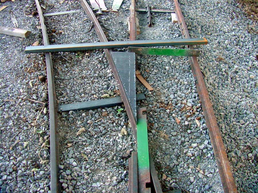
For now we just wedged in a piece of steel to keep the switch locked in the proper position. We are now just waiting on Mel Harris to use his big press to bend the ends of the rail for the derailer guards and cut out the 1" thick frog on his big hacksaw machine.

To figure out the frog we placed a straight edge from the inside edge of the new straight to the inside straight of the new switch and drew a soap stone line. We decided we needed a 6" wide frog at the rear (yellow arrows) and 23.5" long to the point. (red arrow). When the frog is made and the derailer guards are finished and it all lines up we will cut this part of the curve out and weld the other in. That should only take a few hours and then the switch will be fully finished. But until then we still have our original loop functional and in place with no down time.


This is a photo of what the frog area we measured for will look like when finished ... The photo is of one of the #8 switches that Mel Harris built for us else where and we then cut the whole thing in and made the curve to fit them. The in place one we are now building is utilizing our existing curve and is a hybrid #6 switch in as the train is already in the curve 7 feet before it hits the frog, thus no sudden sharp jerk at the frog. This photo shows the frog and inside derailer guards bent on the ends to align with the inside straight and the inside curve. The out side derailer guards need only a little bend on each end wide enough for the wheels to enter safely forward or reverse with room to spare. Our other 3 switches will be just like this one shown above ... just bolt it into one of our existing straights and then build the new curve where we want it.
This is the frog that our machinist Mel Harris
Freehanded with his torch ... thru 1" of solid steel
From the 1" wood template that Dave Moeller made.

Today, Dave Moeller and I put in 127' of double and single rail .. got the inside rail flexed into place ... didn't even need any bars to hold it except at the first joint. We bolted 3 sections together = 90' ... tomorrow we will pull the outside rail into place ... just pull it over till each of the 15 gauge bars drops into place per 30' section. This is another great benefit of steel welded ties, you can leave the flex in the rail and customize and change the radiuses as needed until the weld is put into place.
Below See How We Hooked Up The Full Sized Switchstand

Dig the hole about 1' x 2' and 8" deep.
It will take about 3 sixty lb bags of concrete

Cut a piece of pipe to fit the round swivel arm
Weld a 5/8" steel bar perfectly perpendicular to it.
You want it to almost contact the underside of the ears
to keep it from lifting under the pressure of throwing the switch.

Set the stand on the wet concrete ... If it's mixed properly it will not sink. Level it and align it with the tube the steel bar will run thru. 2 people really helps with this ... I put the last one in by myself and it is a lot harder to do. Then vibrate the bolts down into the concrete ... I used the back side of a grinder .... Let it sit for 24 hours. We wet it down twice later in the day. Today .... later this morning (it's 4 am now) I will tighten the bolts and set the collars to limit the throw distance and then cut off the extra unneeded bar. Oh .. and the 4" long tube I run the bar thru is also a piece of pipe the 5/8" rod fits thru with plenty of room to slide. I welded the center of the tube onto the top of a bolt and double nutted the bottom. The tube should be just loose enough on the 1/2" flat bar so it can pivot from the straight to the curve throws.


Finished switch
This last photo taken by chief engineer and co-builder Dave Moeller
- SEE MORE PHOTOS OF NEW APPROACH AND BRIDGE
- More Phase 3 trackage & rebuilding a Flat Car
- Photo Tour of our almost finished Phase 3
- The best Frogs & switches web site ever!
If you ever have an interest in building your own switch this is the place to start! But ...all the books and conferences you attend will never do it ... you must build it yourself to ever understand all that is involved.
- The Best Railroad Archive Site in the World
The above frogs & switches site is off this home page.
- Return to Our Main Railroad Site
- Return to our Funny Dental Site